User Defined View Plane Icons/Rings
Plane icons are the representation of aircraft on-screen. There are several styles to choose from, see Icon Type below. Range Rings show distance and time around a plane icon. See Range Rings below. Plane Icons and Range Rings are depicted in both Standard and Spherical Projections.
![]() Click to see the User Defined View Plane Icon/Rings
window
Click to see the User Defined View Plane Icon/Rings
window
To Set Plane Icons/Rings:
Click the View Settings icon on the Main toolbar or User Defined View Settings (CTRL +V) on the View menu, and then click Planes -> Plane Icons/Rings.
To Activate a Plane View:
The overlay must be enabled first by clicking the Show Plane Overlay check box in User Defined View Settings -> Planes or by clicking the drop-down arrow on the Plane Overlay icon on the Overlay Toolbar, then selecting Plane View Settings -> Planes.
To turn on the Planes overlay, click the Plane Overlay icon on the Overlay toolbar, or select Planes (ALT + P) on the Overlays menu.
|
Item |
Description |
Steps |
|---|---|---|
|
Icon Type area |
Select the type of icon that will represent aircraft on-screen from |
|
|
Automatic |
This section displays either a jet, propeller, or helicopter icon, depending on the aircraft type. Unknown types can be designated as Jet, Triangle, or Circle. |
|
|
Jet |
Select this option to designate unknown aircraft as a jet symbol on-screen. |
|
|
Isosceles triangle |
Select this option to designate unknown aircraft as a solid triangle on-screen . |
|
|
Circle |
Select this option to designate unknown aircraft as a solid circle on-screen . |
|
|
Plnd & Sched Queue Icons |
Planned and scheduled Queue flights can appear as a cascade of jets or circles each representing a flight. This option is only available in the Queue mode, see the next 2 examples. The total count for Planned and Scheduled flights appear in the Status Bar as PreDep or Pre-Departure. For more information on Queue and Summary modes, see Navigating -> Toolbars -> Plane Toolbar. |
|

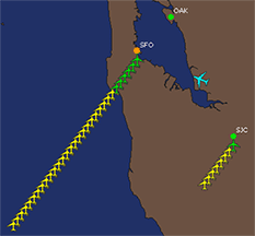
Queue Mode - Jet |
This image represents a Ground Stop (orange) at San Francisco Airport in Queue mode. The icon has been set as a jet. The number of flights are represented by an individual plane. In this case, there are 6 planned and 25 scheduled aircraft.
|
|

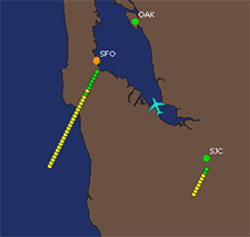
Queue Mode-Circle |
This image represents a Ground Stop (orange) at San Francisco Airport in Queue mode. The icon has been set as a circle. Each circle represents one flight. Notice that one scheduled flight has been moved in front of a planned flight.
|
|
|
Plnd & Sched Summary Icons |
Planned and scheduled Summary flights appear as a single jet icon (see first example), as two jet icons (see second example), or no jet icon. The size of the icon can be changed to a Small or Large Jet or None (jet is replaced with two colored circles). Each style shows the number of flights at the center of the icon or to either side of the single icon. Rest the mouse cursor over one or between both jet icons to see a list of all flights departing the airport, sorted by departure time. Right-click an icon to open the Plane Summary context menu. This context menu can list up to 100 flights at a time, sorted by departure time. Total count for Planned and Scheduled flights appear in the Status Bar as PreDep or Pre-Departure. For more information on Queue and Summary modes, see Navigating -> Toolbars -> Plane Toolbar |
|
|
Single Summary Mode |
This image represents a Ground Delay (orange) at Boston Airport in Single Summary mode.
|
|

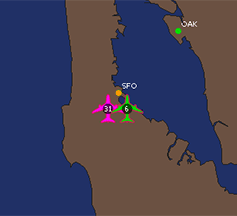
Dual Summary Mode |
This image represents a Ground Stop (orange) at San Francisco Airport in Dual Summary mode.
|
|
|
Draw Icon Outline |
Select this option to place a custom outline around all plane icons or symbols. To select outline color:
|
|
Note When an aircraft takes off, it is first represented by a circle (at all zoom levels). After a second position report is received, and direction can be ascertained, the aircraft symbol changes to that selected above.
Icon Shadow area
Shadows can be added to aircraft icons or symbols by selecting this checkbox. Further customize the shadows by setting the following:
|
Item |
Description |
|
|---|---|---|
|
Draw Icon Shadow |
Select this option to have a shadow follow the aircraft icon on the earth surface. |
|
|
Offset |
Changes the distance of the shadow based on the plane's altitude or pixels (5,10, or 20). |
|
|
Direction |
This option changes the direction of the shadow relative to the plane. Choices are: lower right, lower left, upper right, or upper left. |
|
|
Transparency |
Changes the transparency of the plane shadow for better visibility when using different views and backgrounds. |
|
|
Zoom Level |
Allows you to choose the zoom level at which you would like the planes to be visible on screen. To select the current zoom level of the map window, click the @ button. The corresponding item will be visible from the selected zoom level all the way in to the lowest zoom level (city). |
|
|
Icon Size area |
Select one of these options to customize the size of the plane icon from small, medium, large, or jumbo. |
|
Range Rings |
Select this option to draw distance rings around plane icons at specific ranges such as time, distance, or pixels. The higher the altitude the larger the ring will appear. |
|
|
Draw Range Ring Unit |
Click this option to activate the range ring around an aircraft icon. Select how the rings are to be set for time, distance, or pixels. *RLOS - Radio Line of Sight, is the reach of the transmitter. |
|
|
Minutes (@current speed) Minutes (@ custom speed) - Minutes calculated by a specified speed. Speed of a specific aircraft type set within ACTypes.txt.
|
Minutes calculated at the current aircraft speed. |
|
|
Minutes (@ 389 knots) |
Minutes calculated by 389 knots. |
|
| Miles (fixed) |
Miles calculated by a fixed number. |
|
| Miles (RLOS @ cur alt) |
Miles calculated by the Radio Line of Sight. The Value field is grayed out. |
|
|
Pixels |
Pixels calculated by a specified number of pixels. | |
| Range (FOB@custom speed) |
Conditions:
|
|
|
Range (FOB@current speed) |
The maximum distance an aircraft can travel based on remaining fuel, at the current speed, determines the size of the range ring. The Value field is grayed out. This calculation uses Reserve Fuel from the 3PDI Flight Plan message. |
|
|
Value |
Depending upon the Unit selected above, enter a numerical value such as 5 miles or 60 minutes. |
|
|
Line |
Choose whether there should be a solid visible line with color or no line. |
|
|
Solid None |
To select outline color:
|
|
|
Fill |
Choose whether the ring should be filled in with a color or have none. |
|
|
Solid None |
To select outline color:
|
|
|
Color Density |
Decide if the color selected in Line and Fill above should be Transparent (see through) or Opaque (solid) by moving the slider left or right. |
|
|
Pixel Accurate |
Select this option to have the Range Ring appear as accurate as possible. |
|